Product Overview
- A complete, continuous DP water level measurement loop purpose-built for steam boiler drums, integrating three matched components: Balance Container, 3-Valve Manifold, and DP Transmitter.
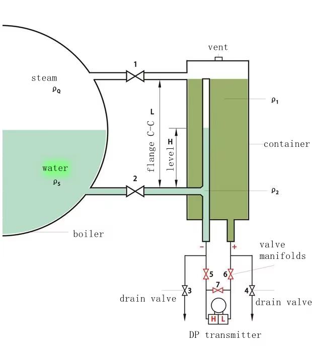
- Uses the hydrostatic (wet-leg) balance method: a fixed condensate reference column is compared against a variable column that tracks the actual drum water level, producing a stable differential pressure signal proportional to level.
- Removes the measurement error caused by steam condensation and temperature variation that affects simple wet-leg transmitter connections.
- Suitable for control, indication, and safety-related level duty on shell-type and water-tube steam boilers.
- Supplied as a coordinated set for straightforward specification, procurement, and installation, and intended to be read together with the boiler manufacturer’s own drum and mounting drawings.
Features
- Twin-chamber Balance Container maintains a constant, temperature-compensated condensate reference column alongside the drum-tracking column, for accurate and stable DP output.
- 3-Valve Manifold with independent HP/LP block valves and a centre equalising valve allows safe zero-checking, isolation, and transmitter removal without depressurising the balance container or interrupting boiler operation.
- Microprocessor-based DP Transmitter (JEP-300) with 4–20 mA output superimposed with HART digital communication, plus integral LCD local indication.
- High accuracy: ±0.1% of full span.
- Compact balance container footprint (DN20 flanges, 400 mm standard flange centre-to-centre) rated up to 160 barg / 400°C.
- SIL2-capable transmitter variants available for safety-instrumented (trip) functions per IEC 61508 / IEC 61511.
- ATEX-certified transmitter variant available for installation in classified hazardous areas.
- Materials of construction (SS304 standard, SS316/316L on request) suited to corrosive feedwater or chloride-bearing environments.
- Freeze-protection provisions (heat tracing/insulation) supported for cold-climate installations.
Technical parameter
Balance Container
- Type: Twin-chamber (double-wall) condensate balance vessel
- Wetted material: Stainless steel SS304 (SS316/316L available on request)
- Process connection: DN20 flanges, both ports (EN 1092-1)
- Flange centre-to-centre distance: 400 mm standard (alternative on request)
- Design pressure: up to 160 barg
- Design temperature: up to 400°C
DP Transmitter (PI305X-TSD / CST305X-DPT)
- Measuring range: −4 to +4 kPa (adjustable span within range)
- Output signal: 4–20 mA with superimposed HART protocol
- Local indication: integral LCD display
- Power supply: 12–24 VDC, 2-wire loop-powered
- Accuracy: ±0.1% of full span
- Ambient temperature range: −20°C to +80°C
- Ingress protection: IP56
- Wetted materials: stainless steel diaphragm and body (typical); Hastelloy/tantalum options available for aggressive media
3-Valve Manifold
- Configuration: HP block valve, LP block valve, centre equalising valve
- Body material: forged stainless steel (carbon steel option available)
- Pressure rating: matched to Balance Container design pressure (20 barg)
- Operation: hand-wheel actuated, packed-gland stem
Industry application
- Continuous water level indication for steam boiler drums (shell-type and water-tube boilers) in control-room display systems.
- Automatic feedwater control loops.
- High/high and low/low level alarm and safety interlock (trip) duty.
- Power generation, process steam, and industrial utility boiler installations.
- Applications requiring compliance with EU pressure equipment, EMC, and boiler safety-device standards as part of a CE-marked boiler assembly.
Applicable EU Directives and Standards
| Reference | Subject |
|---|---|
| Directive 2014/68/EU (PED) | Pressure Equipment Directive — governs pressure-retaining parts (Balance Container, manifold) |
| EN 12952 series (Parts 7 & 11) | Water-tube boilers — water-level indicating and limiting equipment |
| EN 1092-1 | Circular flanges — basis for DN20 connections |
| EN 10204 | Material inspection documents (3.1/3.2 certificates available on request) |
| Directive 2014/30/EU (EMC) | Electromagnetic Compatibility — transmitter electronics and HART output |
| Directive 2014/35/EU (LVD) | Low Voltage Directive — transmitter DC supply circuit |
| Directive 2014/34/EU (ATEX) | For hazardous-area installation (certified variant on order) |
| IEC 61508 / IEC 61511 | Functional safety — SIL2-capable variants available |
| Directive 2011/65/EU (RoHS) | Restriction of Hazardous Substances |
Note: This is a technical solution summary. Certification documents, material certificates, and the applicable conformity-assessment route must be confirmed with the manufacturer at the time of order.