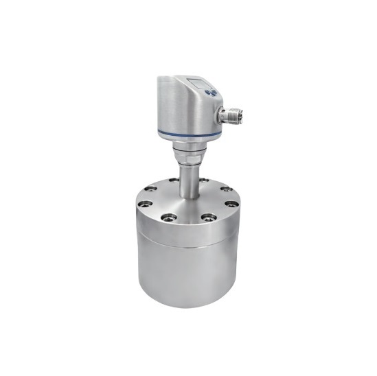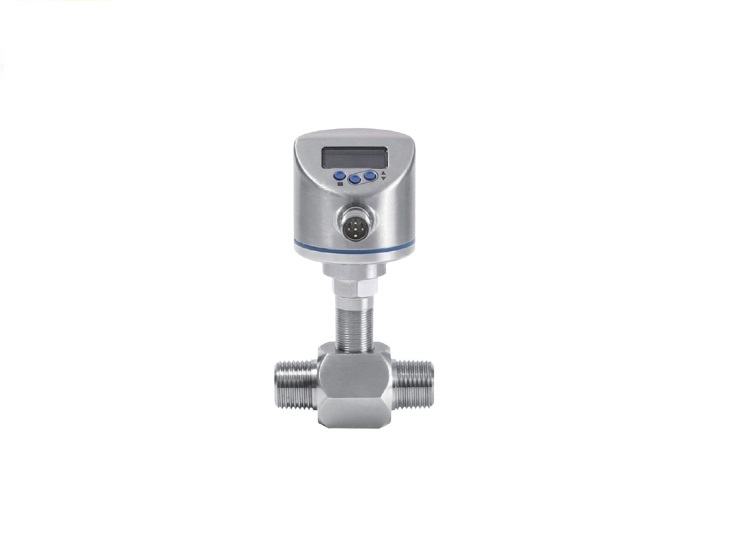
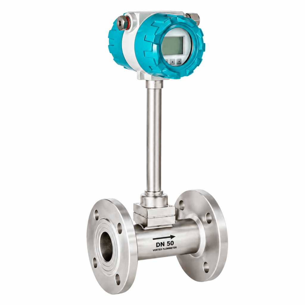
Product Overview
The CST-VXW series is engineered to cover a broad span of pipe sizes, process connections and output configurations, allowing a single product platform to serve liquid, gas and steam applications across light industry, process industry and utility metering.
Connection / Body Styles
- Flange type (DN15–DN300): full-bore flanged meter body for permanent in-line installation, offered as standard to DIN PN16 flange connections (other flange standards available on request).
- Wafer type (DN15–DN300): compact, lightweight body clamped between existing line flanges — a cost-effective option where installation space is limited.
- Insertion type (DN80–DN2000): probe-style sensor for hot-tap installation on large-diameter pipework, suited to utility and large process lines without requiring the line to be cut.
- Thread / sanitary type (DN15–DN100): small-bore threaded or hygienic tri-clamp connections for compact piping and sanitary process lines.
Transmitter Configuration
- Integral (compact) type: electronics housing mounted directly on the sensor body — a self-contained, easy-to-install unit.
- Remote type with temperature & pressure compensation: electronics housing mounted separately from the sensor, with built-in compensation for temperature and pressure to output true mass or standard-volume flow, particularly for saturated and superheated steam service.
Materials & Certification
- Wetted materials: SS304 stainless steel as standard, with SS316 available as an option for corrosive or higher-purity service.
- Hazardous area rating: ATEX Ex ia IIC T5 Ga, for use in explosive atmospheres where certified equipment is required.
Electrical Output
- Signal output: 4–20 mA analogue output plus pulse output, standard on all variants.
- Digital communication: HART protocol or RS485 (Modbus) — selectable at time of order.
Features
- No moving parts: the Karman vortex-shedding principle requires no moving mechanical parts in the flow path, giving high long-term reliability and minimal maintenance.
- Multi-medium measurement: a single meter platform measures liquid, gas and both saturated and superheated steam.
- Wide rangeability: liquid velocity range of 0.4–7.0 m/s, gas velocity range of 4.0–60.0 m/s and steam velocity range of 5.0–70.0 m/s, giving a wide usable turndown for varying process loads.
- High accuracy: ±1.0% of reading for flange/wafer types and ±1.5% of reading for insertion types.
- Mass-flow capability: optional integrated temperature and pressure compensation delivers direct mass or standard-volume flow output for steam and gas applications, removing the need for separate compensation instruments.
- Flexible outputs: 4–20 mA plus pulse output as standard, with a choice of HART or RS485 Modbus digital communication for integration with DCS/SCADA/PLC systems.
- Wide process range: process temperature from –40°C to +250°C as standard, extending to +350°C with the high-temperature variant; nominal pressure ratings of 0.6, 1.0, 1.6, 2.5 and 4.0 MPa.
- Vibration tolerant: rated for vibration acceleration up to 0.2 g, with installation guidance available for high-vibration pipelines.
- Hazardous-area ready: ATEX Ex ia IIC T5 Ga explosion-proof certification available for installation in classified zones.
- Flexible power options: line-powered (DC 12–30 V) or battery-powered (3.6 V lithium) for remote or unpowered metering points.
- Broad size coverage: DN15–DN300 for flange/wafer types and DN80–DN2000 for insertion types, covering small utility lines through to large main pipework.
- Corrosion-resistant construction: SS304 standard wetted parts, with SS316 available for demanding process media.
Technical Parameters
Basic Technical Parameters
| Parameter | Specification |
| Measured Medium | Liquid, Gas, Steam |
| Medium Temperature | -40°C to +250°C (standard); -40°C to +350°C (high-temperature type) |
| Nominal Pressure | 0.6 MPa, 1.0 MPa, 1.6 MPa, 2.5 MPa, 4.0 MPa |
| Accuracy | ±1.0% (flange / wafer type); ±1.5% (insertion type) |
| Flow Velocity Range | Liquid: 0.4–7.0 m/s | Gas: 4.0–60.0 m/s | Steam: 5.0–70.0 m/s |
| Nominal Size | DN15–DN300 (flange / wafer type); DN80–DN2000 (insertion type); DN15–DN100 (thread / sanitary type) |
| Wetted Material | SS304 (standard); SS316 (optional) |
| Reynolds Number | 2×10⁴ – 7×10⁶ (normal operating range) |
| Resistance Coefficient (Cd) | ≤ 2.6 |
| Vibration Acceleration Allowed | ≤ 0.2 g |
| Explosion-proof Rating | ATEX Ex ia IIC T5 Ga |
| Ambient Temperature | -40°C to +65°C (non-explosion-proof site); -20°C to +55°C (explosion-proof site) |
| Relative Humidity | ≤ 85% |
| Ambient Pressure | 86–106 kPa |
| Power Supply | DC 12–30 V, or 3.6 V lithium battery |
| Signal Output | 4–20 mA, Pulse |
| Digital Communication | RS485 (Modbus) or HART |
Standard Flow Range Reference (Flange / Wafer Type, DN15–DN300)
The table below gives indicative flow ranges for the flange and wafer body styles; the insertion type covers DN80–DN2000 with ranges determined by installation and pipe conditions.
| Nominal Size DN (mm) | Liquid (m³/h) | Air / Gas (m³/h) | ||
| Standard Range | Extended Range | Standard Range | Extended Range | |
| 15 | 0.8-6 | 0.5-8 | 6-40 | 5-50 |
| 20 | 1-8 | 0.5-12 | 8-50 | 6-60 |
| 25 | 1.5-12 | 0.8-16 | 10-80 | 8-120 |
| 32 | 2-20 | 1.5-25 | 15-150 | 10-200 |
| 40 | 2.5-30 | 2-40 | 25-200 | 20-300 |
| 50 | 3-50 | 2.5-60 | 30-300 | 25-500 |
| 65 | 5-80 | 4-100 | 50-500 | 40-800 |
| 80 | 8-120 | 6-160 | 80-800 | 60-1200 |
| 100 | 12-200 | 8-250 | 120-1200 | 100-2000 |
| 125 | 20-300 | 12-400 | 160-1600 | 150-3000 |
| 150 | 30-400 | 18-600 | 250-2500 | 200-4000 |
| 200 | 50-800 | 30-1200 | 400-4000 | 350-8000 |
| 250 | 80-1200 | 40-1600 | 600-6000 | 500-12000 |
| 300 | 100-1600 | 60-2500 | 1000-10000 | 600-16000 |
Saturated Steam Mass Flow Range (kg/h)
Reference mass-flow range (minimum Qmin to maximum Qmax) by nominal size and steam absolute pressure, for saturated steam service.
| Absolute Pressure (MPa) | 0.2 | 0.3 | 0.4 | 0.5 | 0.6 | 0.7 | 0.8 | |
| Temperature (°C) | 120.2 | 133.5 | 143.62 | 151.84 | 158.94 | 164.96 | 170.41 | |
| Density (kg/m³) | 1.129 | 1.651 | 2.163 | 2.669 | 3.17 | 3.667 | 4.162 | |
| 15 | Qmin | 5.645 | 8.255 | 10.815 | 13.345 | 15.85 | 18.335 | 20.81 |
| Qmax | 56.45 | 82.55 | 108.15 | 133.45 | 158.5 | 183.35 | 208.1 | |
| 20 | Qmin | 6.774 | 9.906 | 12.978 | 16.014 | 19.02 | 22.002 | 24.972 |
| Qmax | 67.74 | 99.06 | 129.78 | 160.14 | 190.2 | 220.02 | 249.72 | |
| 25 | Qmin | 9.032 | 13.208 | 17.304 | 21.352 | 25.36 | 29.336 | 33.296 |
| Qmax | 135.48 | 198.12 | 259.56 | 320.28 | 380.4 | 440.04 | 499.44 | |
| 32 | Qmin | 20.322 | 29.718 | 38.934 | 48.042 | 57.06 | 66.006 | 74.916 |
| Qmax | 203.22 | 297.18 | 389.34 | 480.42 | 570.6 | 660.06 | 749.16 | |
| 40 | Qmin | 22.58 | 33.02 | 43.26 | 53.38 | 63.4 | 73.34 | 83.24 |
| Qmax | 338.7 | 495.3 | 648.9 | 800.7 | 951 | 1100.1 | 1248.6 | |
| 50 | Qmin | 28.225 | 41.275 | 54.075 | 66.725 | 79.25 | 91.675 | 104.05 |
| Qmax | 564.5 | 825.5 | 1081.5 | 1334.5 | 1585 | 1833.5 | 2081 | |
| 65 | Qmin | 45.16 | 66.04 | 86.52 | 106.76 | 126.8 | 146.68 | 166.48 |
| Qmax | 903.2 | 1320.8 | 1730.4 | 2135.2 | 2536 | 2933.6 | 3329.6 | |
| 80 | Qmin | 67.74 | 99.06 | 129.78 | 160.14 | 190.2 | 220.02 | 249.72 |
| Qmax | 1354.8 | 1981.2 | 2595.6 | 3202.8 | 3804 | 4400.4 | 4994.4 | |
| 100 | Qmin | 112.9 | 165.1 | 216.3 | 266.9 | 317 | 366.7 | 416.2 |
| Qmax | 2258 | 3302 | 4326 | 5338 | 6340 | 7334 | 8324 | |
| 125 | Qmin | 169.35 | 247.65 | 324.45 | 400.35 | 475.5 | 550.05 | 624.3 |
| Qmax | 3387 | 4953 | 6489 | 8007 | 9510 | 11001 | 12486 | |
| 150 | Qmin | 225.8 | 330.2 | 432.6 | 533.8 | 634 | 733.4 | 832.4 |
| Qmax | 4516 | 6604 | 8652 | 10676 | 12680 | 14668 | 16648 | |
| 200 | Qmin | 395.15 | 577.85 | 757.05 | 934.15 | 1109.5 | 1283.45 | 1456.7 |
| Qmax | 9032 | 13208 | 17304 | 21352 | 25360 | 29336 | 33296 | |
| 250 | Qmin | 564.5 | 825.5 | 1081.5 | 1334.5 | 1585 | 1833.5 | 2081 |
| Qmax | 13548 | 19812 | 25956 | 32028 | 38040 | 44004 | 49944 | |
| 300 | Qmin | 677.4 | 990.6 | 1297.8 | 1601.4 | 1902 | 2200.2 | 2497.2 |
| Qmax | 18064 | 26416 | 34608 | 42704 | 50720 | 58672 | 66592 | |
| Absolute Pressure (MPa) | 0.9 | 1.0 | 1.2 | 1.4 | 1.6 | 1.8 | 2.0 | |
| Temperature (°C) | 175.36 | 179.68 | 187.96 | 195.04 | 201.37 | 207.11 | 212.37 | |
| Density (kg/m³) | 4.665 | 5.147 | 6.127 | 7.106 | 8.085 | 9.065 | 10.05 | |
| 15 | Qmin | 23.325 | 25.735 | 30.635 | 35.53 | 40.425 | 45.325 | 50.25 |
| Qmax | 233.25 | 257.35 | 306.35 | 355.3 | 404.25 | 453.25 | 502.5 | |
| 20 | Qmin | 27.99 | 30.882 | 36.762 | 42.636 | 48.51 | 54.39 | 60.3 |
| Qmax | 279.9 | 308.82 | 367.62 | 426.36 | 485.1 | 543.9 | 603 | |
| 25 | Qmin | 37.32 | 41.176 | 49.016 | 56.848 | 64.68 | 72.52 | 80.4 |
| Qmax | 559.8 | 617.64 | 735.24 | 852.72 | 970.2 | 1087.8 | 1206 | |
| 32 | Qmin | 83.97 | 92.646 | 110.286 | 127.908 | 145.53 | 163.17 | 180.9 |
| Qmax | 839.7 | 926.46 | 1102.86 | 1279.08 | 1455.3 | 1631.7 | 1809 | |
| 40 | Qmin | 93.3 | 102.94 | 122.54 | 142.12 | 161.7 | 181.3 | 201 |
| Qmax | 1399.5 | 1544.1 | 1838.1 | 2131.8 | 2425.5 | 2719.5 | 3015 | |
| 50 | Qmin | 116.625 | 128.675 | 153.175 | 177.65 | 202.125 | 226.625 | 251.25 |
| Qmax | 2332.5 | 2573.5 | 3063.5 | 3553 | 4042.5 | 4532.5 | 5025 | |
| 65 | Qmin | 186.6 | 205.88 | 245.08 | 284.24 | 323.4 | 362.6 | 402 |
| Qmax | 3732 | 4117.6 | 4901.6 | 5684.8 | 6468 | 7252 | 8040 | |
| 80 | Qmin | 279.9 | 308.82 | 367.62 | 426.36 | 485.1 | 543.9 | 603 |
| Qmax | 5598 | 6176.4 | 7352.4 | 8527.2 | 9702 | 10878 | 12060 | |
| 100 | Qmin | 466.5 | 514.7 | 612.7 | 710.6 | 808.5 | 906.5 | 1005 |
| Qmax | 9330 | 10294 | 12254 | 14212 | 16170 | 18130 | 20100 | |
| 125 | Qmin | 699.75 | 772.05 | 919.05 | 1065.9 | 1212.75 | 1359.75 | 1507.5 |
| Qmax | 13995 | 15441 | 18381 | 21318 | 24255 | 27195 | 30150 | |
| 150 | Qmin | 933 | 1029.4 | 1225.4 | 1421.2 | 1617 | 1813 | 2010 |
| Qmax | 18660 | 20588 | 24508 | 28424 | 32340 | 36260 | 40200 | |
| 200 | Qmin | 1632.75 | 1801.45 | 2144.45 | 2487.1 | 2829.75 | 3172.75 | 3517.5 |
| Qmax | 37320 | 41176 | 49016 | 56848 | 64680 | 72520 | 80400 | |
| 250 | Qmin | 2332.5 | 2573.5 | 3063.5 | 3553 | 4042.5 | 4532.5 | 5025 |
| Qmax | 55980 | 61764 | 73524 | 85272 | 97020 | 108780 | 120600 | |
| 300 | Qmin | 2799 | 3088.2 | 3676.2 | 4263.6 | 4851 | 5439 | 6030 |
| Qmax | 74640 | 82352 | 98032 | 113696 | 129360 | 145040 | 160800 | |
Overall Dimensions — Flange Connection (DIN PN16 reference)
| Size (DN) | L (mm) | H (mm) | d (mm) | D1 (mm) | D2 (mm) | n-D3 |
| 15 | 170 | 440 | 15 | 65 | 95 | 4-φ14 |
| 20 | 170 | 445 | 20 | 75 | 105 | 4-φ14 |
| 25 | 170 | 450 | 26 | 85 | 115 | 4-φ14 |
| 32 | 170 | 462 | 32 | 100 | 140 | 4-φ18 |
| 40 | 190 | 465 | 38 | 110 | 150 | 4-φ18 |
| 50 | 190 | 473 | 48 | 125 | 165 | 4-φ18 |
| 65 | 220 | 487 | 62 | 145 | 185 | 4-φ18 |
| 80 | 220 | 500 | 73 | 160 | 200 | 8-φ18 |
| 100 | 240 | 533 | 95 | 180 | 220 | 8-φ18 |
| 125 | 260 | 560 | 118 | 210 | 250 | 8-φ18 |
| 150 | 280 | 608 | 140 | 240 | 285 | 8-φ22 |
| 200 | 300 | 640 | 200 | 295 | 340 | 12-φ22 |
| 250 | 360 | 705 | 250 | 355 | 405 | 12-φ26 |
| 300 | 400 | 752 | 300 | 410 | 460 | 12-φ26 |
Note: dimensions are given in millimetres for the DIN PN16 flanged configuration; wafer, insertion and alternative flange standards are available on request.
Industry Application
With its ability to measure liquid, gas and steam within a single product platform, and its option for temperature/pressure-compensated mass-flow output, the CST-VXW Vortex Flow Meter is suited to a wide range of industrial metering applications, including:
- Power generation & boiler plants: saturated and superheated steam mass-flow measurement for boiler efficiency monitoring, steam distribution metering and heat-energy accounting.
- Oil, gas & petrochemical: flow measurement of process gases, compressed air and hydrocarbon liquids in refining, processing and pipeline metering points.
- Chemical & petrochemical processing: monitoring of process liquids and gases, with SS316 wetted parts available for corrosive media.
- HVAC & utility energy management: compressed air, steam and hot/chilled water metering for plant utility monitoring and energy accounting.
- Food, beverage & pharmaceutical: sanitary/thread connection variants for hygienic process lines and utility metering in regulated production environments.
- Water & wastewater treatment: liquid flow measurement across treatment and distribution processes.
- Metallurgy, cement & heavy industry: high-temperature gas and steam flow monitoring in furnace, kiln and process heating applications.
For hazardous-area installations, the ATEX Ex ia IIC T5 Ga certified variant extends this coverage to classified zones across the above industries.